3d model to 2d drawing creo
Creo: Learn The Basics In 1 60 minutes
![]()
Also known equally PTC Creo, Creo is a multipurpose 3D modeling software for CAD, CAM, CAE. This software caters to everything: product design, development, and manufacturing. Creo was initially called Pro/engineering when information technology was released by PTC in 1987. Its release was considered to be one of the most notable milestones of the evolution of CAD. Over the years, Creo has gone through various changes and improvements. The latest version, Creo 6.0 has a portfolio of highly avant-garde tools and features for modeling and pattern, simulation and analysis, rendering and animation, product data management, and manufacturing.
Due to its many capabilities and high functionality, first-fourth dimension users often find Creo difficult to navigate, regardless of previous experience with other CAD software. In that location is and so much to learn virtually what Creo'southward features are and how to use them, that learning to use the software can be quite daunting. To make your learning process much easier, we at Scan2CAD have created this compact, comprehensive, and intuitive article that will familiarize you with all the basics of Creo in as little as i hour. This article covers the software's capabilities, tools, features, and graphical user interface (GUI). It likewise covers certain procedures and concepts, likewise equally the basics of modeling in Creo.
Creo capabilities
The first thing you need to larn about a software plan is what the software can do. Y'all need to be able to answer the question, "what tin Creo practice?". So what are Creo'southward features, capabilities, features, and tools? Creo's features can be classified into modeling and design, simulation and analysis, CAM , product data direction, performance advisor, and technical illustrations.
Modeling and design
Creo's modeling and design features allow you to create detailed 3D prototypes in a virtual environment. You lot can do this using one of two approaches, direct modeling in which you tin pull and push directly on geometry, and parametric modeling in which all components are related and a modify in one will result in a alter in all. Creo's capabilities nether 3D blueprint are as follows.
- 2nd Drawing
- Model-Based Definition
- Design Exploration
- Sheet Metal Design
- Mechanism Design
- Structural Framework & Weld Design
- Fastener Design
- Human Factors Design
- Routed Systems Blueprint
- Smart Connected Blueprint
- Concept Design
- Plastic Function Design
- Industrial Design
- Opposite Engineering
- Multi-CAD
- Rendering & 3D Blitheness
- Assembly Direction & Performance
Simulation and analysis
With Creo, you tin can acquit out several advanced assay on your model in real-life conditions using the following analysis.
- Structural Assay
- Thermal Analysis
- Motion Analysis
- Mold Fill up Assay
- Fatigue Analysis
- Creepage & Clearance Analysis
Using these tools, yous can save 30-fifty% of your design time equally y'all tin skip physical tests.
-
-
You MIGHT Also LIKE:
PTC Acquires OnShape - Coffee Break News
CAM
Creo bridges the gap between 3D CAD and manufacturing, especially for 3D printing. Now y'all can design for 3D printing without errors, validate and optimize your design, and bear out a impress check, all in one surroundings. This profoundly reduces time, endeavour, and errors. You tin can also print directly from the Creo environment. All you lot need to do is send your design directly to a compatible printer. In improver to 3D press capabilities, Creo is especially useful in designing parts for CNC manufacturing. With this software's NC and tooling capabilities, yous tin can achieve the highest level of precision and quality in as little fourth dimension equally possible. Creo's CAM features tin can be classified as follows.
- Additive Manufacturing
- Tool & Die Design
- Production Machining
Production data management
On average, engineers and designers lose a whopping 25% of their product development time to data management. This time is spent updating systems, sharing data, searching for files, and recreating data. With Creo's cloud-based PDM capabilities, you can easily manage, share, and review data.
Technical illustrations
These features permit y'all to produce highly detailed 3D technical illustrations, second drawings, and animations that correctly project product configurations. The core features of technical illustrations are 3D blitheness, isometric viewing, CAD file conversions, office lists, 2nd detailing and note, and CAD data reuse.
-

-
YOU MIGHT Besides Similar:
Compared: The ten Best 3D CAD Software
Before you become started
Now that nosotros know what Creo can do, and before we explore its graphical user interface (GUI), there are some things well-nigh Creo that we need to familiarise ourselves with. Various file types can be created in Creo and each of these files have unlike GUIs, and also different subtypes. These files are as follows.
Sketch files are 2d sketches of a model. The features in this file'southward window allow you to create detailed 2nd drafts using various tools such equally line, arc, circle, polygon, pigment, and dimension. The sketch window is a 2D drafting interface.
Part files with .prt file extension are private 3D models. A part file is a unmarried component which may be standalone, such as a cup, or part of an assembly, such as a piston. Subtypes of the part file in Creo are solid, canvass metallic, and bulk.
Assembly files, on the other hand, are 3D models of assemblies of various individual parts. The piston given every bit an case above is an individual function merely comes together with other individual parts such as connecting rods and shafts to form an assembly of a motor engine. Assembly files have the .asm file extension.
The .drw drawing files are second drawings of modeled parts in Creo. Drawing files are drafting documents that incorporate annotations, detailed dimensions, role lists, title blocks, and various views of a model such every bit isometric and orthographic. There are several templates for drawing files available in Creo.
Launch screen user interface
When you launch Creo, you showtime come across the launch screen. The launch screen is relatively elementary compared to nearly CAD software. There are three major portions of the launch screen. The menu bar, the PTC browser, and the navigation panel.
At the topmost area of the screen is located the menu bar. The carte of the launch screen contains some useful commands such every bit New, to first a new project; Open, to open an existing session; Open last session, to open the session you lot were last working on; Select working directory, to choose file destination; Appearance settings, for editing both system settings and model display settings; and other useful commands. In addition to these, there is the familiar File button which drops down diverse commands, and the quick access toolbar, both fastened to the card bar.
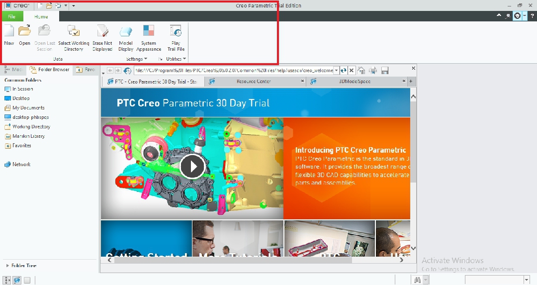
Launch screen menu bar
To the left of the screen is the navigator which contains the Model tree, Favorite binder, and the Binder browser.
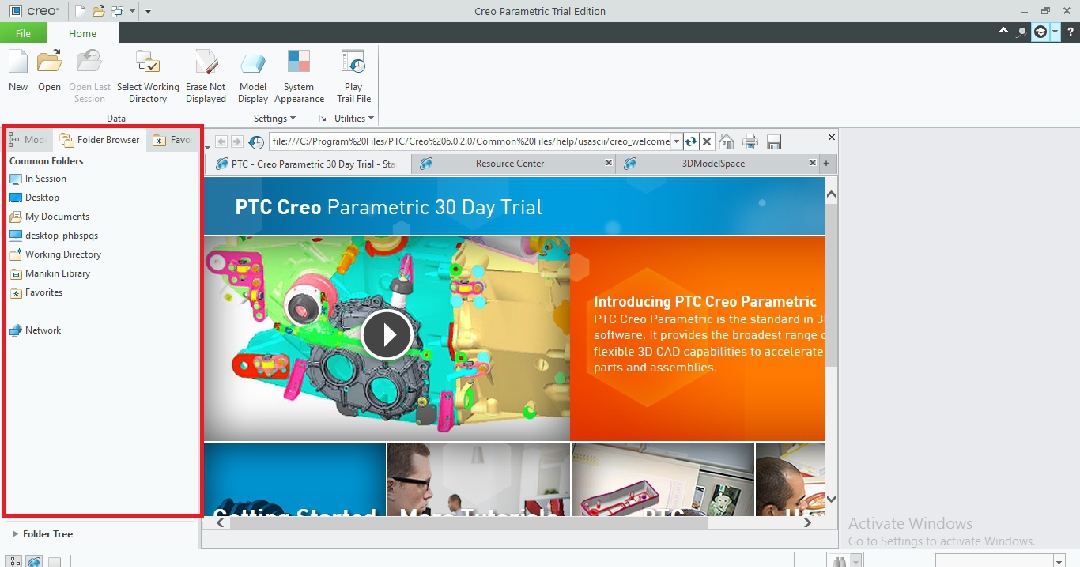
Launch screen navigation console
In the center of the launch screen, taking up the largest area is the PTC browser. The browser launches automatically whenever you launch Creo. Yet, you can hibernate or show the browser to reveal space, using the browser icon at the bottom left corner of the launch screen.
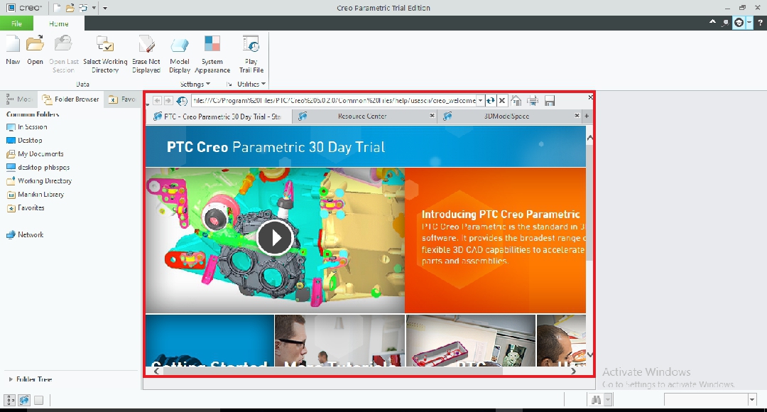
PTC Creo browser
Getting started
Every bit nosotros stated earlier, the different file types in Creo have different Interfaces. This means that the window for creating a part is different from the window for creating an assembly or a cartoon. For the bulk of design projects, the cosmos of parts is usually the starting time footstep. Because of this, and besides because we are dealing with the nuts, we volition just be focusing on the part cosmos GUI.
To create a part from scratch, click on the New icon on the menu bar, the quick access toolbar, or in the drop-downwardly of the file push. This opens a dialogue box displaying the file types in Creo. Select Part and choose the subtype. Next, input the pattern name, which is the name the part file volition conduct, and common proper noun, which is like a model clarification. At the bottom of the dialogue box is a checkbox to use the default template for the file type you have selected. We recommend that yous uncheck this box before clicking OK and so that you can alter the template to adapt your preferences.
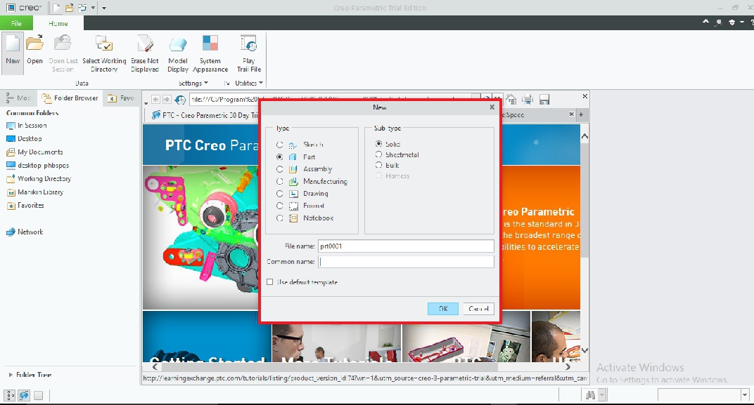
Dialog box containing part file types
After unchecking the box, click OK to be directed to some other dialogue box from which you tin select from several templates. A template has to do with which standard (ANSI, ISO, etc) and unit you will work with. In this dialogue box, you tin can input your name as the designer of the projection. This time, nosotros recommend that you check the Re-create associated drawings checkbox, as this will ensure that your selected template for the role is reflected in its associated drawings. Adjacent, click OK to be redirected to the main Function drawing interface/window.
Part creation window
Similar to the launch screen, the part creation window is roughly divided into three distinct sections, the Characteristic ribbon, the navigation panel, and the drawing surface area.
The navigation console simply like in the launch screen is located to the left of the window. Information technology contains three tabs, the model tree, the folder browser, and the favorite folder.
Located just above the Feature ribbon is the quick access toolbar. It contains some commonly used commands like new, open, salve, redo, and undo. The quick access toolbar besides contains your nearly frequently used tools.
The feature ribbon contains all the tools and features you lot need to model, analyze, view, interact with, and edit your model. It is located at the top of the screen, just below the quick admission toolbar. The tools and features in the feature ribbon are neatly organized into panels, with the panels themselves organized into tabs. Each tab is defended to a particular procedure in your office cosmos procedure. The tabs in the Feature ribbon are model, analysis, comment, render, tools, view, flexible modeling, and applications.
The Model tab contains the bulk of the modeling tools. Using the tools in this tab, you lot tin can sketch, extrude, apply shapes, add features, identify patterns, edit, change planes, alter surfaces, and more than. The tools are organized into the following panels; operations, get data, datum, shapes, engineering, edit, surfaces and model intent.
The next tab is the Analysis tab. This tab contains tools that allow you lot to perform various measurements and perform various types of simulation and analysis of your model. The panels in this tab are manage, custom, model written report, mensurate, audit geometry, and design written report.
The Annotate tab comes next. This tab is for creating 3D annotations, peculiarly if you employ model-based definitions. The tools in the comment tab are organized into panels every bit follows; combination states, association planes, manage annotations, note features, datum, and annotations.
Following the comment tab is the render tab. The tools in this tab enable yous to create high-quality photo-realistic images of your model. This allows y'all to view the real-life advent of your model while it is withal in the blueprint stage. The panels in this tab include appearance, perspective render. and setup.
In line with its proper name, the Tools tab contains numerous tools and commands for various purposes such as find, publish geometry, and model planner. The tools in this tab are organized into 3 panels; investigate, model interior, and utilities.
The View tab has a variety of tools needed to alter the visibility and appearance of both your model and the modeling window. You lot can zoom, pan, change advent, and preview. The panels in the view tab are visibility, orientation, model brandish, show, and window.
Next is the Flexible modeling tab which allows you to incorporate direct modeling techniques into Creo.
Finally, we take the Applications tab. This tab allows you to switch to other different modules such as PTC math CAD for doing applied science mathematics.
Back to the office creation window. The centrally located drawing area makes upward about 60% of the part creation window. This is where you lot carry out the actual modeling. The drawing area is the canvas on which you draw, model, simulate, detail, collaborate with your model, and on which your project is displayed. You can zoom in/out the drawing area nigh infinitely.
At the lesser of the Drawing area is the status bar where you lot can show or hide the navigation plane and Creo browser. Y'all can too detect Activity history where all your actions in a particular project are recorded.
-

-
Y'all MIGHT Likewise LIKE:
How Much Does Creo Cost? Pricing Explained
Nuts of modeling in Creo
Having familiarized ourselves with the part interface, nosotros can now proceed to the actual modeling. In Creo, whatsoever part no matter how complex begins with a sketch. To brainstorm modeling, click on Sketch in the Model tab. Adjacent, select a plane in the drawing area. After you've selected a plane, the Sketch push button volition expand into a tab of its own, revealing several sketching tools like circle, line, arc, and rectangle. Click on whatever of this and then click on whatever point on the drawing area. Drag your mouse to determine the size of the shape yous selected. Repeat these steps, selecting and adding different shapes until y'all form the base shape of your model. Click on OK to finish sketching and to reactivate the model tab where you can extrude the shape past any desired length. From here you tin can add holed, fillet, add patterns, sketch on the model surface, bend, sweep, and many more.
Recommended resources
Creo is a highly functional 3D modeling software with thousands of features and tools. This article has covered the basics, providing you with an fantabulous foundation for Creo mastery. To learn more than nigh Creo and become a Creo professional, visit the following sites.
- PTC university
- PTC support
- Udemy Pro Engineer Creo Fundamental 3D design course
schermerhornsaffive.blogspot.com
Source: https://www.scan2cad.com/blog/cad/creo-basics/
0 Response to "3d model to 2d drawing creo"
Post a Comment